HMI CONTROLLER FOR ARDUINO
|
The Hmi Controller for Arduino is an application for the Android OS that allows you to connect your Arduino board (UNO and Mega) with your Android device in an easy way, it can be connected over Bluetooth or LAN (Local Area Network), without the need of understanding anything about Android programming, also without the need of knowing a lot of functions or writing extended code in your Arduino sketch to make the communication. Hmi Controller manages all the control process of the pins and variables declared in your Arduino project.
Make your own customizable hmi in the app without the need of a computer, you can select from eight different objects (widgets): button, switch, led, display 7 segments, numeric display, bar indicator, slider and graph. Never as it been so easy to control your Arduino board! |
|
|
The Widgets
You can find seven different components (widgets) to interact with your Arduino, which are divided into two groups. The first group are the input widgets that are conform by:
The second group of widgets are the output widgets, these are:
Note: The input widgets sends data to the Arduino board and the output widgets reads data from the Arduino board.
- Button: Is used with the variables pin-out and virtual-boolean-in. In the configuration box in the app, only requires a name tag and the variable which is going to be associated.
- Switch: Used the same variables like the button widget and it have the same configuration box.
- Slider: It changes a variable of type int from a min value to a max value, it acts like a potentiometer. It's compatible only with the virtual-int-in variable. In the configuration box, it requires to put the name tag, the min value, the max value and the variable to associate.
The second group of widgets are the output widgets, these are:
- Led: This widget turns on or off according to the state of the associated variable. The variables to associate are: pin-out, pin-in and virtual-boolean-out. It only requires the variable to associate and a name tag.
- Display 7 segments: It show an integer number from 0 to 9999, the associate variable is the virtual-int-out. It only requires the variable to associate and a name tag.
- Numeric display: Can show any numeric value of an int, long or float number. It only requires the variable to associate and a name tag.
- Bar Indicator: This widget shows the state of a variable from a min to a max value, the associate variable is the virtual-int-out. In the configuration box, it requires to put the name tag, the min value, the max value and the variable to associate.
- Graph: It shows the information of a virtual-int-out variable in the time domain. The time of the graphic can be adjusted with a scale of time of 30 secs, 60 secs, 5 min, 30 min and 60 min.
Note: The input widgets sends data to the Arduino board and the output widgets reads data from the Arduino board.
Types of variables
The Hmi Controller use six different types of variables for the interaction between the application and the Arduino board, this variables are:
- pin-in: This variable represents a physical INPUT pin of the Arduino board. In the full version this variable must be declared using “Hmi.pinMode()” function, for the lite version the variable is automatically declared when the Arduino “pinMode” function is used in the sketch.
- pin-out: It represents a physical OUTPUT pin of the Arduino board. In the full version this variable must be declared using “Hmi.pinMode()” function, for the lite version the variable is automatically declared when the Arduino “pinMode” function is used in the sketch.
- virtual-boolean-in: It's a boolean variable used as an "IN" data from the app to the Arduino. It can be declared in the hmi system by using the “Hmi.attachBooleanIn()” function.
- virtual-boolean-out: It's a boolean variable used as an "OUT" data from the Arduino board to the app. It can be declared in the hmi system by using the “Hmi.attachBooleanOut()” function.
- virtual-int-in: It's an int variable used as an "IN" data from the app to the Arduino. It can be declared in the hmi system by using the “Hmi.attachIntIn()” function.
- virtual-int-out: It's an int variable used as an "OUT" data from the Arduino board to the app. It can be declared in the hmi system by using the “Hmi.attachIntOut()” function.
- virtual-long-in: It's a long variable used as an "IN" data from the app to the Arduino. It can be declared in the hmi system by using the “Hmi.attachLongIn()” function.
- virtual-long-out: It's a long variable used as an "OUT" data from the Arduino board to the app. It can be declared in the hmi system by using the “Hmi.attachLongOut()” function.
- virtual-float-in: It's a float variable used as an "IN" data from the app to the Arduino. It can be declared in the hmi system by using the “Hmi.attachFloatIn()” function.
- virtual-float-out: It's a float variable used as an "OUT" data from the Arduino board to the app. It can be declared in the hmi system by using the “Hmi.attachFloatOut()” function.
Functions for Arduino
One of the great advantages of this app is that the programing of the Arduino to make the communication is very easy and simple, there are a series of functions that make this possible, those are:
In order to use the Hmi Controller with your Arduino board, you must implement one of the following functions at the end of your sketch:
Note 1: If in your code you're making a loop that ends when a specific variable or an input pin has changed, you must also include one of this functions inside that loop.
Note 2: For more understanding take a look at the examples.
- Hmi.isConnected(); (NEW FUNCTION)
- Hmi.pinMode(pin, mode);
- Hmi.attachLongIn(long variable, char letter); (NEW FUNCTION)
- Hmi.attachLongOut(long variable, char letter); (NEW FUNCTION)
- Hmi.attachFloatIn(float variable, char letter); (NEW FUNCTION)
- Hmi.attachFloatOut(float variable, char letter); (NEW FUNCTION)
- Hmi.attachIntIn(int variable, char letter);
- Hmi.attachIntOut(int variable, char letter);
- Hmi.attachBooleanIn(boolean variable, char letter);
- Hmi.attachBooleanOut(boolean variable, char letter);
In order to use the Hmi Controller with your Arduino board, you must implement one of the following functions at the end of your sketch:
- Hmi.softSerial(SoftwareSerial mySerial): Is used when you're implementing a Bluetooth connection with the Arduino SoftwareSerial library, this is recommended to be used when implementing the Arduino UNO and Arduino micro.
- Hmi.hardSerial(HardwareSerial mySerial): Is used when you're implementing a Bluetooth connection with the Arduino HardwareSerial library, this is recommended to be used when implementing the Arduino Mega.
- Hmi.nEthernet(Server myServer): Is used when you're implementing an Arduino Ethernet shield.
Note 1: If in your code you're making a loop that ends when a specific variable or an input pin has changed, you must also include one of this functions inside that loop.
Note 2: For more understanding take a look at the examples.
INSTALLING THE HMI CONTROLLER FOR THE FULL AND THE LITE VERSION
The Hmi Controller full version can be found for downloading from here and the lite version from here, once you have it installed in your Android device, you must download the HMI Controller library for Arduino from here and installed in your Arduino IDE, this library is compatible with the last version of Arduino IDE.
The HMI library needs the Standard C++ library for Arduino, you can get it from here.
The HMI library needs the Standard C++ library for Arduino, you can get it from here.
UPDATING THE HMI LIBRARY FOR ARDUINO (NEW)
If you already have installed a previous version of the HMI library for Arduino in your Arduino IDE you must update it to the version 2.0 that can be download from here. Copy and paste the content of the HMI library 2.0 in the folder “libraries\Hmi” of your computer where the Arduino IDE it’s installed.
DIFFERENCES BETWEEN FULL AND LITE VERSION
One difference is that the lite version is free but with not all the features from the full version, the widgets available in this version are: switch, led, bar indicator, display 7 segments and numeric display.
In the full version the user can add widget into five different tables, in the lite version the user can only add widget to one table. The full version have 10 save slots, the lite version have 3 save slots.
The Full version doesn't have ads.
In the full version the user can add widget into five different tables, in the lite version the user can only add widget to one table. The full version have 10 save slots, the lite version have 3 save slots.
The Full version doesn't have ads.
CHANGE BACKGROUND
HMI allows you to change the background on each table, this gives more personalization to your project. To change the background, copy your image file into the “Backgrounds” folder located in the “HMI Data” or “HMI Lite Data” folder of your Android device, the file must be in .jpg format.
In order for HMI to find your image, you must change the name of the file with “backgroundX.jpg”, where the “X” is the number of the table. For example, for the table #0 the name is “background0.jpg”, for the table #3 the name is “background3.jpg”.
To get the proper width and height of the image go to the menu of the app, then to the “About” option and tap the “Resolution” button.
To add the images into the HMI folder, use the file manager of your Android device, the HMI folders will not be shown in the PC file explorer.
EXPORT / IMPORT A HMI DESIGN TO OTHER ANDROID DEVICE (NEW)
You can export or import a HMI design to other Android device that use the same version of HMI Controller for Arduino.
EXPORT DATA: In order to export a hmi design you must open the design to export and once open select the “Export Data” option that it’s available in the main menu > “Export / Import”. The exported file can be located at “HMI Data\Export” or “HMI Lite Data\Export” folder of your Android device.
IMPORT DATA: In order to import a hmi design you must put the “my_File.hmi” file you want to import in the “HMI Data\Import” or “HMI Lite Data\Import” folder of your Android device, then open the HMI app and select the “Import Data” option that it’s available in the main menu > “Export / Import” and then save it in a save slot of your election.
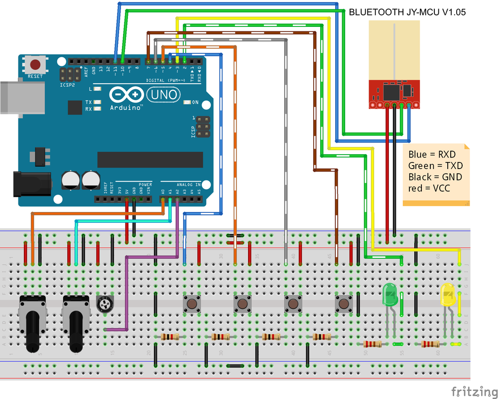
USING THE HMI CONTROLLER WITH BLUETOOTH
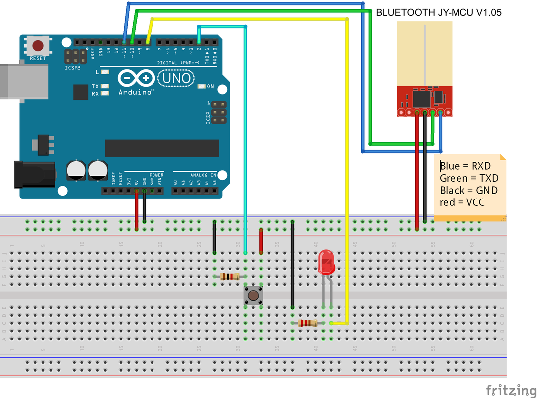
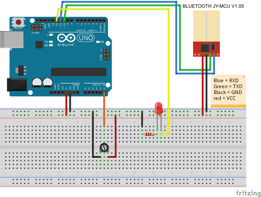
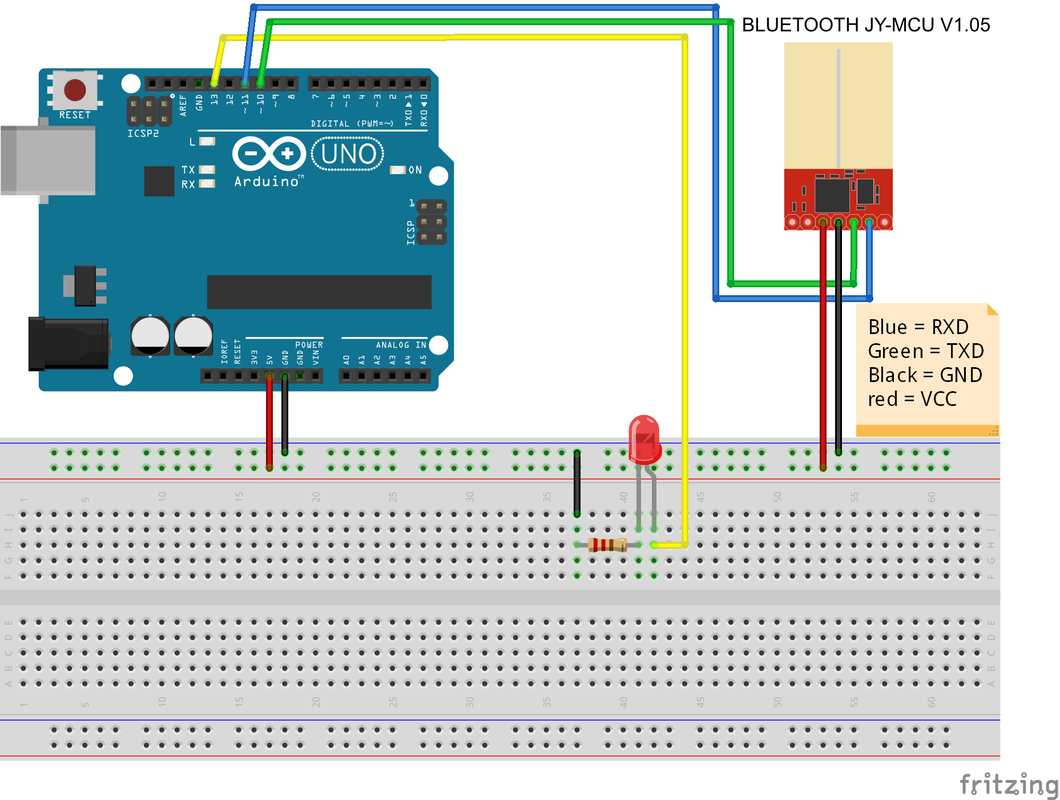
In order to use the app with a Bluetooth connection, it's necessary to have a Bluetooth module, in case you don't have one, you can get one here at a low price. The module used in this guide is the JY-MCU HC-06.
The module use a serial communication with the Arduino so it can be connected in the serial ports that are between the pin 14 to pin 19 when using an Arduino Mega. On an Arduino Uno and Nano the serial pins are the pin 0 and pin 1. The adapter can also be connected in other pins declared as serial pins with the Software Serial library.
1. Connect the Bluetooth module to the Arduino board.
2. Connect the Arduino to the computer.
3. Open the Arduino IDE for HMI Controller.
4. Write or open a sketch with the HMI functions in it, there are some examples below that you can use.
5. Load the sketch to the Arduino board.
6. Turn ON the Bluetooth in the Android device. In case that the Arduino Bluetooth module isn't paired with Android continue with the next point , otherwise go to step number eight.
7. Go to the Bluetooth settings in the Android settings, make your Android visible to all nearby Bluetooth devices and tap the "search for devices" button. The pairing password of the JY-MCU HC-06 module is 1234.
8. Open the HMI Controller app in the Android device, select "Bluetooth" in the type of connection dialog box and select your Arduino Bluetooth module.
9. To add a widget go to Edit -> "Add widget" that's in the action bar, the "Edit" button looks like a pencil.
10. Once all the widgets are in place according to the desired design, tap the "Play" button to begin the connection. (Only for the Lite version)
USING THE HMI CONTROLLER WITH A LOCAL AREA NETWORK
For the connection of the app with the Arduino board over a LAN (Local Area Network) it requires the Arduino Ethernet Shield.
1. Connect the Ethernet Shield to the Arduino board.
2. Plug the RJ-45 cable to the Ethernet Shield.
3. Connect the Arduino to the computer.
4. Open the Arduino IDE for HMI Controller.
5. Write or open a sketch with the HMI functions in it.
6. When using the Ethernet functions in the sketch is important to set the IP address, the subnet or mask, the gateway and the MAC for the Ethernet Shield, other things to keep in mind is the number of the port, this number must be set to the port number 23.
7. Load the sketch to the Arduino board.
8. Open the HMI Controller app in the Android device, select "LAN (Ethernet Shield)" in the type of connection dialog box.
9. Set the IP address of the Arduino board, the same IP that was configured in the Arduino sketch.
10. To add a widget go to Edit -> "Add widget"that's in the action bar, the "Edit" button looks like a pencil.
11. Once all the widgets are in place according to the desired design, tap the "Play" button to begin the connection. (Only for the Lite version)
ARDUINO MEMORY CONSIDERATIONS
- The HMI Controller uses great part of the Arduino SRAM, so it's important to know the type of applications that's going to be used, for big projects with a lot of variables it's recommended to use the Arduino Mega, for small to medium projects the Arduino UNO and the Nano will do the job.
- There are more use of SRAM when using the Ethernet Shield than the Bluetooth module.
EXAMPLES
For an easy understanding of how to use the app with the Arduino IDE, there are three examples, each one with the Arduino .ino file and the examples can be found in menu of the app.
- Accessing only the pins of the Arduino:
|
| ||||
- Attaching and using the virtual int variables:
|
| ||||
- Attaching and using the virtual boolean variables:
|
| ||||
- Car example:
|
| ||||
ARDUINO TEMPLATES
|
|
| ||||||
© 2017 Sergio Daniel Castañeda N . All rights reserved.
